902 Orion RX
A long time ago I wanted to make a 33cm Ham repeater using nothing but Orion radios… the 900Mhz Orion will TX in 927 just fine but I was told no Orion will RX in 902… so I decided to try and modify the 800Mhz Orion to RX in 902Mhz because I wanted an all-Orion repeater…
I honestly can’t remember much of what I did seeing as this was 6~7 years ago but it all began with some trial and error (mostly error)
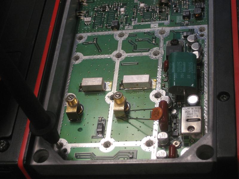
Playing with caps till I managed to get the VCO Line to 5v…
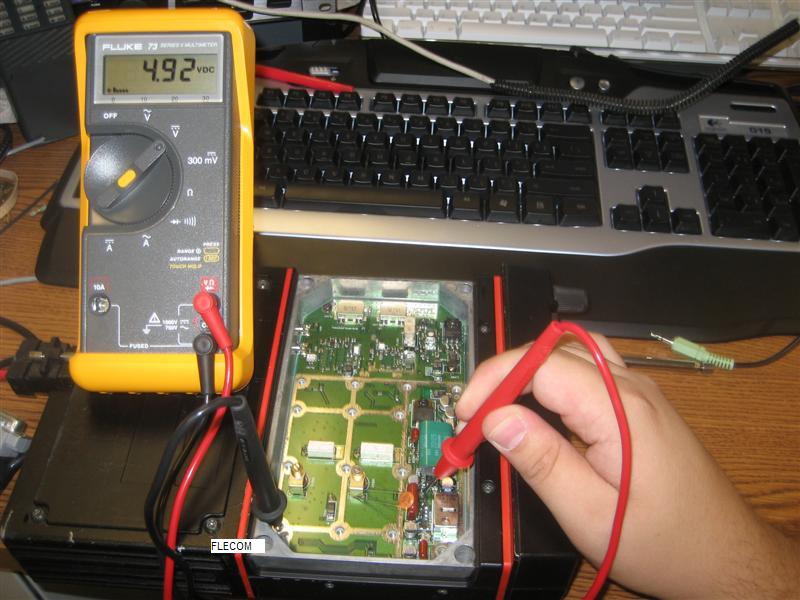
Success!
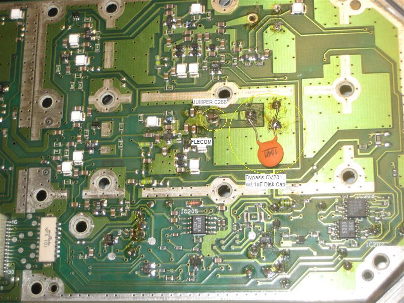
Obviously this isn’t an ideal part but it did the job… solder in place…
Result…
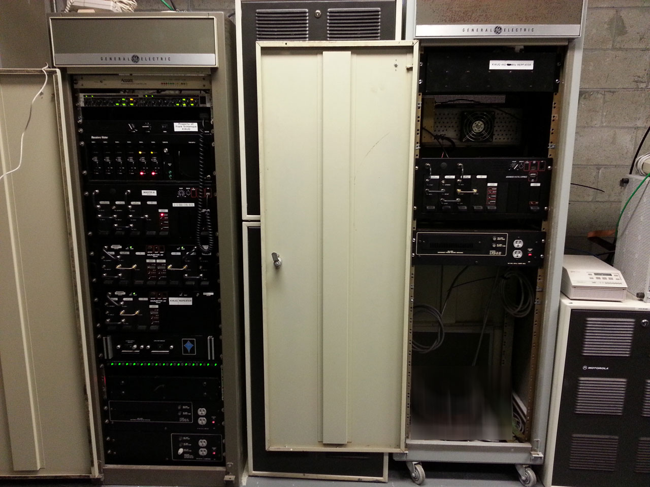
Finally ended up integrating it into a little /\/\otorola desktop repeater cabinet with a home-made dual radio cable that also goes to a DB-25 to interface with a CAT-2oo repeater controller (not pictured was used later in another repeater) along with a 900Mhz Orion for TX along with a small power supply and a mobile duplexer… the 800Mhz PA was removed to save a bit of weight… used the flex ribbon from the PA for it’s DB37 interface and a coax pigtail from an MTX or something like that can’t remember…
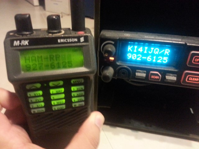
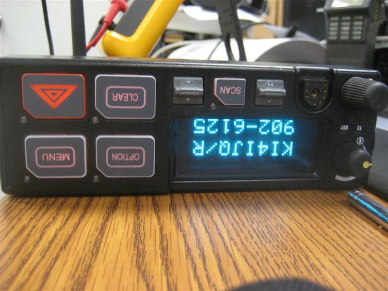
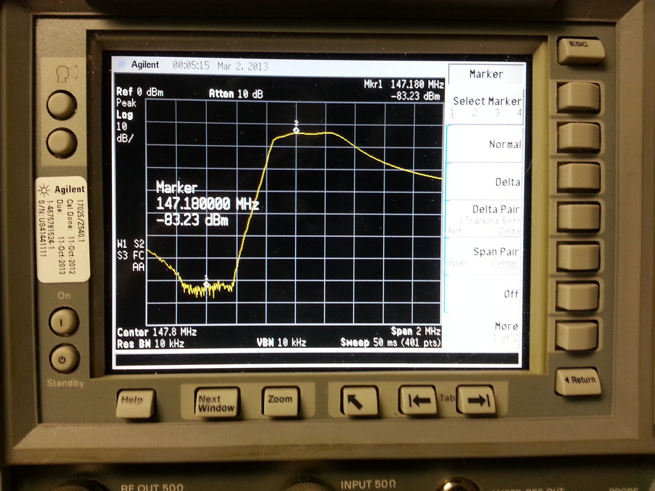
800Mhz Orion RX’ing 902Mhz
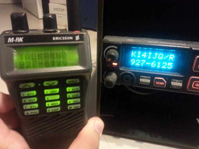
Since it was setup in a dual-radio config if you TX in Talk Around the 900Mhz Orion will show RX’ing
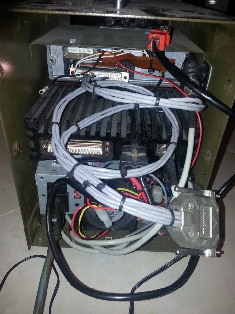
Home-Made Dual Radio cable along with the DB-25 connector for going to the CAT-200 Repeater Controller (missing)
Two things that are not really mentioned is you must remove/replace (or in my case just bypass) the filter on the RX side or the radio will be incredibly deaf… bypassing the filter the radio is about -118 ~ -120 or so which is not bad… additionally if you do use a disk cap (ideally you would use a proper cap) you need to glue it down with some hot glue or something if not the radio will be incredibly micro phonic…
Strange fortunes?
The Vietnamese restaurant I go to has the strangest fortune cookies, but they are usually humorous… this one has to be one of my favorites though…

Server Upgrade – Again…
Well the ram helped but spun up some more VMs and resources were getting stretched again so decided to drop in another Intel Xeon L5639 and 24Gb DDR3 into it, should do nicely!
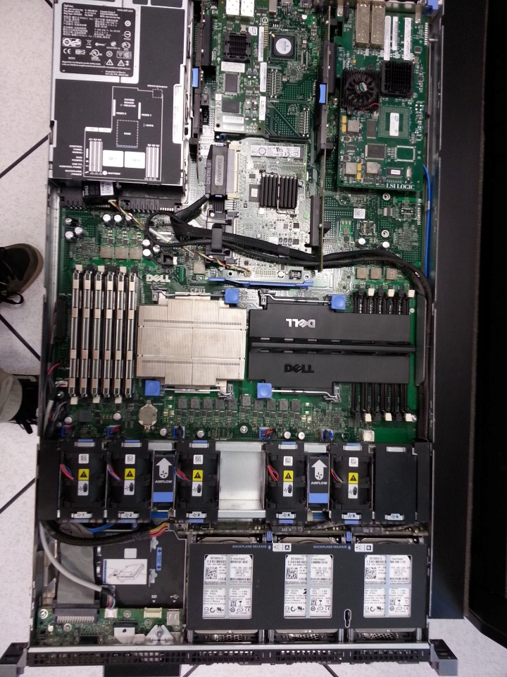
Before…
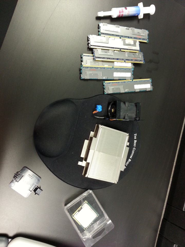
Incoming bits…
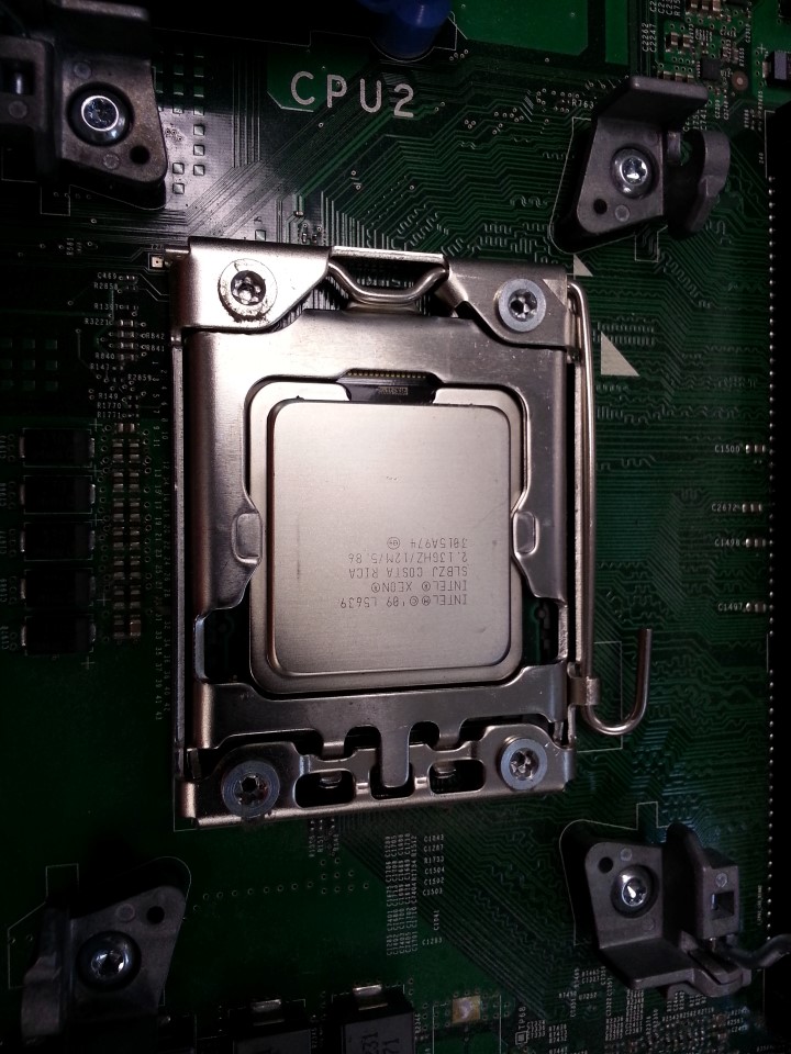
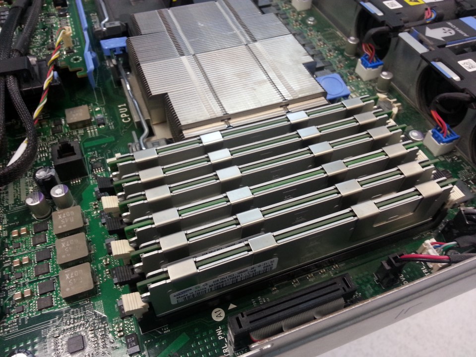
Xeon in its new home…
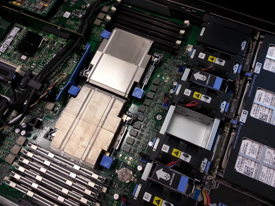
Dell proprietary heatsink attached…
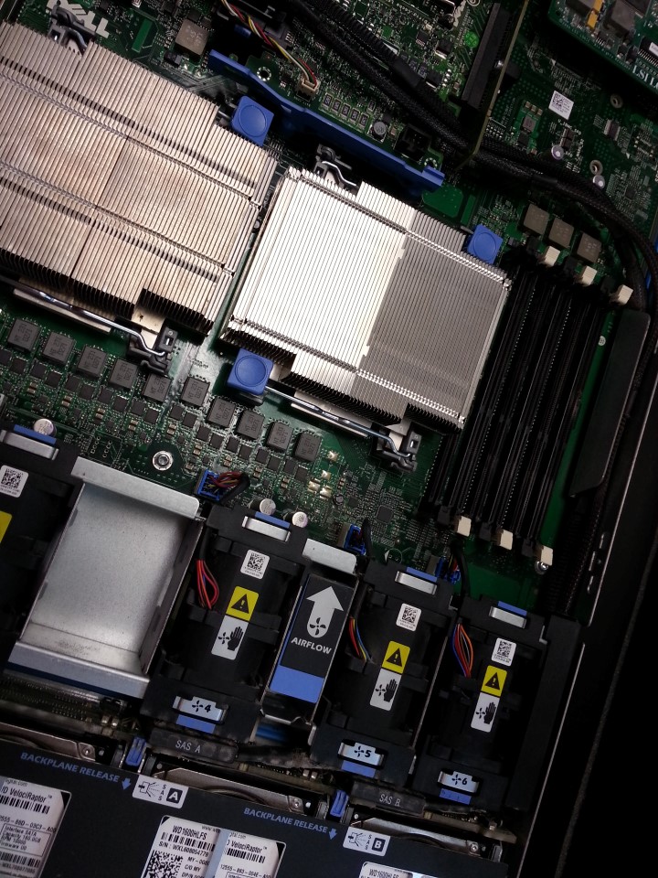
Extra fan module installed…
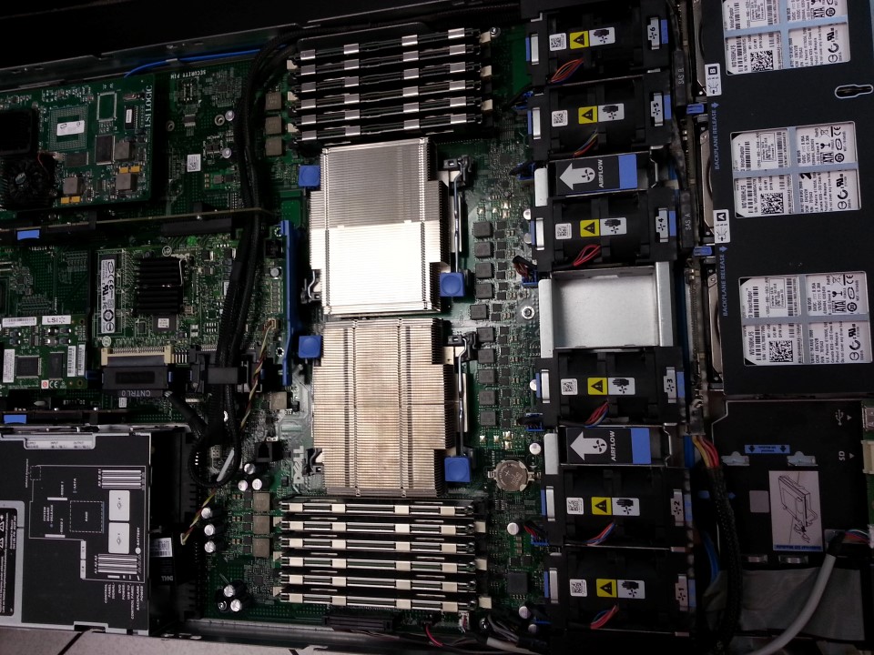
Finally another 24Gb ram bringing it up to 48Gb ram…
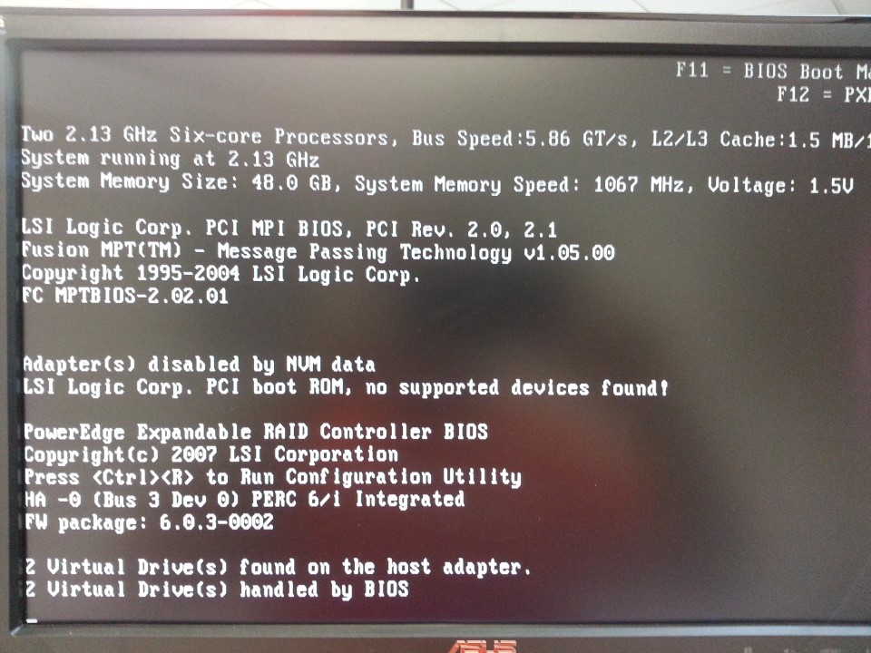
All done!
Little Shop of Games Open House…
Curley from Little Shop of Games had his annual open house today…
Good food, good people, and great pins as per the usual make it a must-go event 🙂
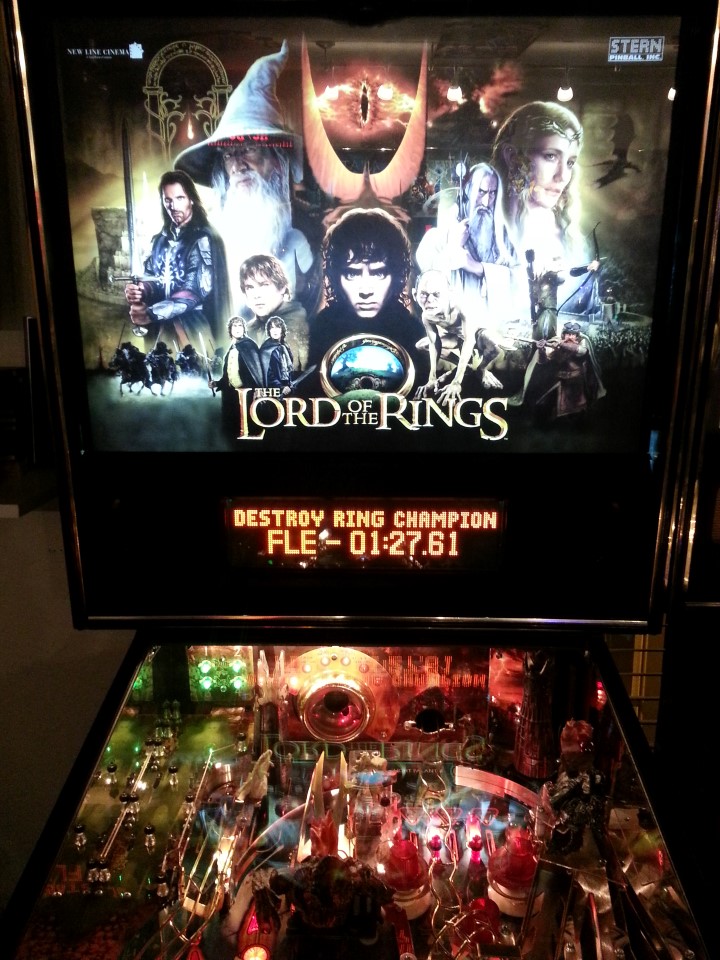
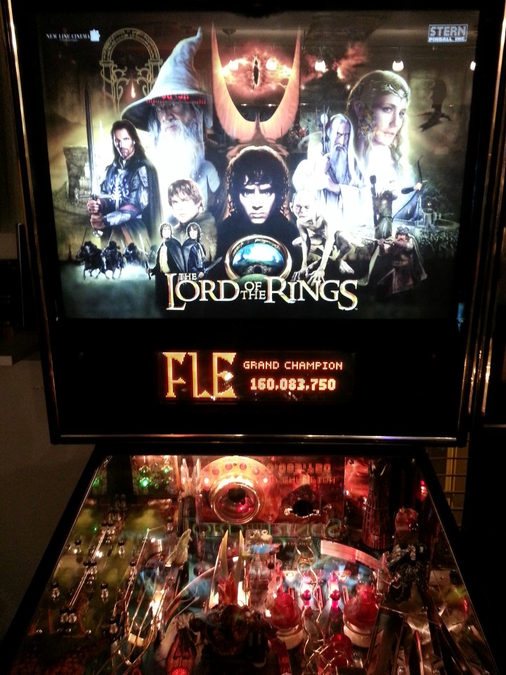
Also managed to get a nice score on a LoTR but unfortunately couldn’t afford to take it home with me!
Server Upgrades…
Some much needed server upgrades tonight… Upgraded my Dell R610 from 6Gb ram to 24Gb ram… going to make VMWare much happier!
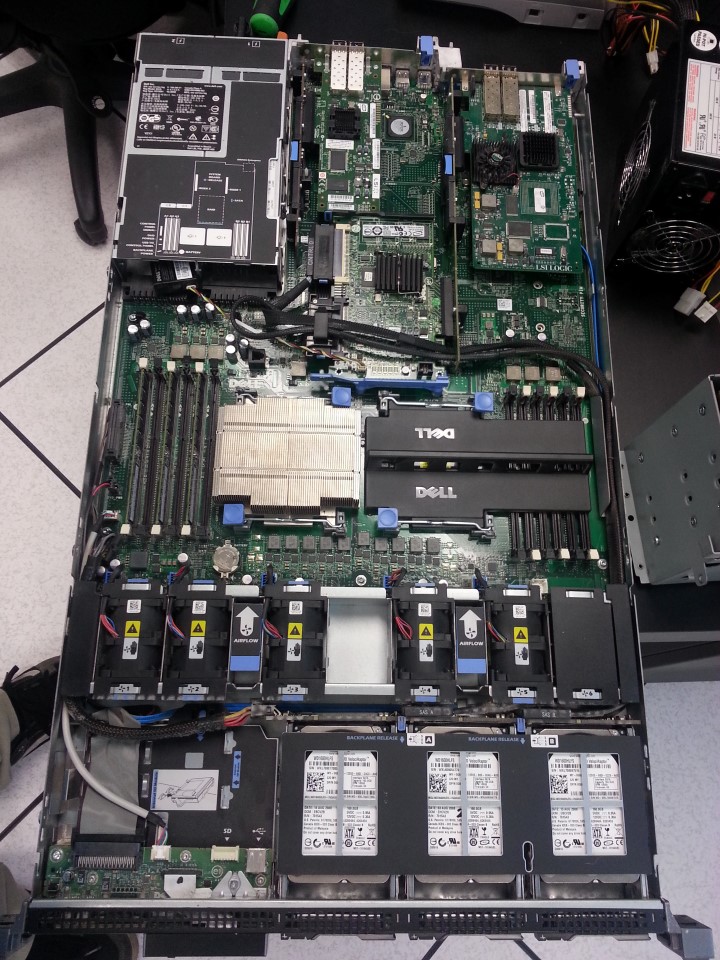
Before…
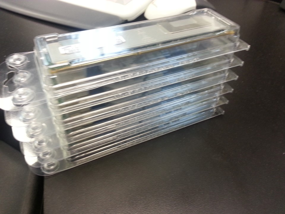
24Gb DDR3 ECC
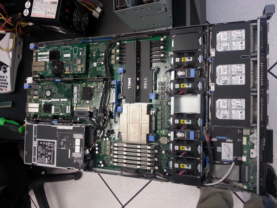
After…
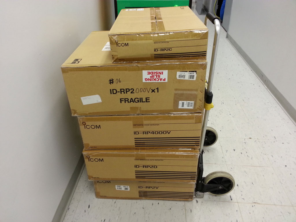
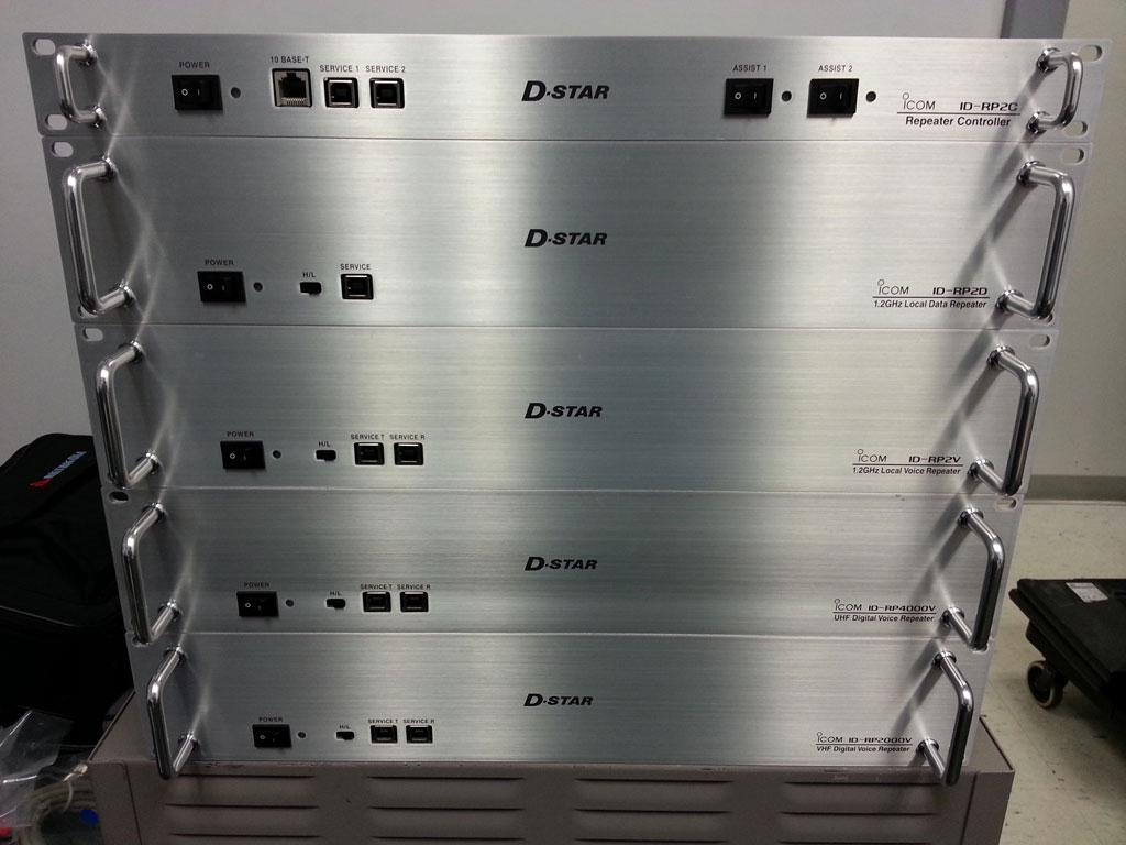
D-Star*
Well as if I needed more projects to work on – the Dade Radio Club has asked me to take over their ICom D-Star repeater project…
Sadly I know chances are nobody will ever use any of this stuff but hey at least it looks really pretty!
DE KI4IJQ/R
Finally got the new repeater on the air, now just have to get remote sites for voting… the goal is county-wide hand held coverage… but have to start somewhere…