Archive for July, 2012
Modifying Pinball GI Circuits for DC Part 1: WPC95 Theory
/EDIT: UPDATE: This did not really work out as planned, need to look at the data on the scope and see exactly what is happening with these SCR’s…
So the theory was incorrect :sadface:
I am going to do a series of articles on modifying Pinball GI circuits for DC (to run LEDs instead of incandesant lamps) in order to get rid of annoying 60hz strobing/flicker.
Part 1: Williams WPC95
The Williams WPC95 was the last of William’s pinball machines board systems (before Pinball 2000). The board used 3 TRIACs to control 3 GI circuits each capable of driving 18 lamps and 2 “always on” circuits generally used for the backbox (boring! more on that later).

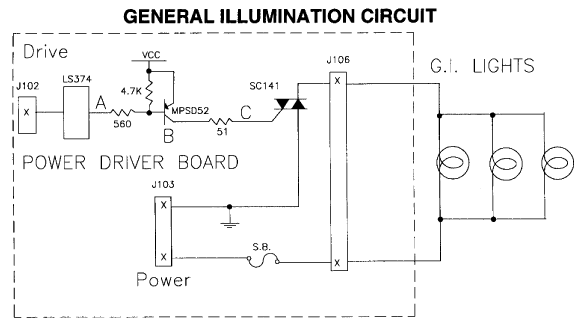
Ok so here is a quick GI block diagram/theory of operation from a WPC95 game manual. Data from the CPU board comes in via J102, selects a 74LS374, which drives a MPSD52 (2N5401) which then drives a TRIAC that lets the AC flow from J103 (6.3VAC secondary from power transformer) to J105 which goes to the controlled GI lamps.
(Click for larger version)
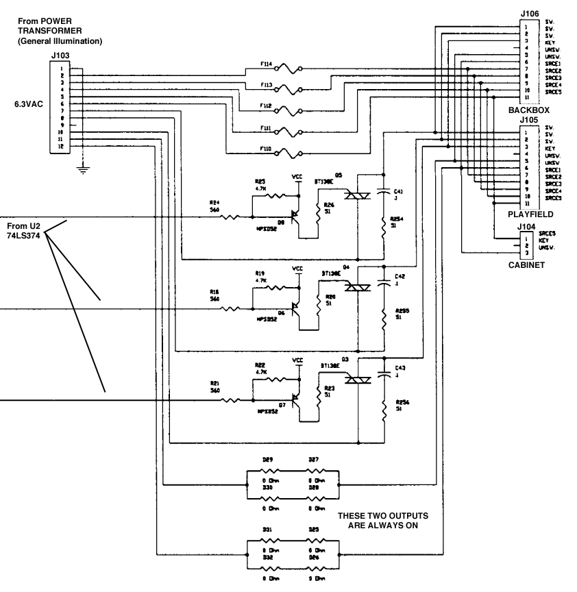
Here is the actual relevant part of the WPC95 schematic (from the WPC95 manual). You can see the three data lines coming from U2 (74LS374), driving the three MPSD52 (2N5401) and then driving the three TRIACs. TRIACs are pretty neat devices, basically like a transistor but for AC instead of DC (see: https://en.wikipedia.org/wiki/TRIAC), but since we want to use DC for our GI LEDs they need to go. If you notice the general layout of this circuit is very similar to other repeating circuts on the Power Driver board including the solenoid and general purpose driver outputs, so we are basically just going to copy those and insert them in place of the original TRIAC based one.
Doing that gives us this
(Click for larger version)
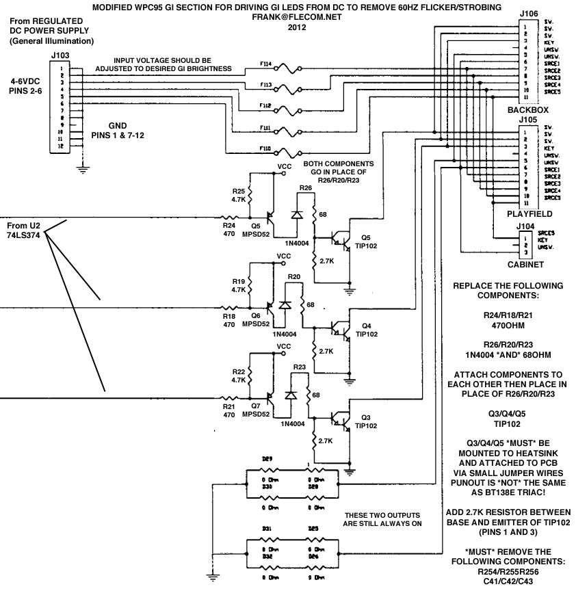
Ok so here we have replaced the TRIAC (Q3, Q4, Q5) with TIP102s (for the sake of keeping things the same) one important thing to note immediately is that the TIP102 does *NOT* have the same pinout as the BT138E TRIACs we are removing, so the easiest way to deal with that is simply mount the transistor onto the heatsink upside down, and solder some bits of wires to the leads and then run those leads to the pads on the board in the correct order. You also need to add a 2.7K resistor between the Base and Emitter of the TIP102 as indicated in the schematic, you can just attach the resistor straight to the transistor between pins 1 and 3.
Additionally the following needs to be done to the board:
The 560 ohm resistors at R24/R18/R21 need to be replaced with 470 ohm resistors
The 51 ohm resistor at R26/R20/R23 need to be replaced with 68 ohm resistors AND a 1N4004. Simply attach both devices to each other in a V shape and then insert in place of R26/R20/R23
Additionally (and not pictured in the schematic) you can add some large capacitors on the output of the TIP102s to try and smooth out the PWM that Williams machines use to “dim” the GI circuits, with LEDs you just get a really noticeable strobing instead of the desired dimming, but adding a large cap should “smooth out” the PWM enough to at least suppress the strobing to tolerable levels.
Finally and a very important note, you can NOT put AC straight into this circuit, it either requires separate rectification/filtering/regulation of the GI secondary coming from the main power transformer, or a small DC switching supply which is what I generally use. Small 5v switchers are readily available and provide a “5v” adjust which usually gives you a little play in the output voltage, allowing you to dim or brighten the GI LEDs as desired.
Pictures of the actual modifications coming soon!
Tales of the Arabian Nights & Playchoice 10
Have 2 new items in the collection, first is my grail pin, Tales of the Arabian Nights, an excellent top 10 Williams machine from 1996… Unfortunately it has quite a bit of insert issues, with many of them flaking off, and/or becoming raised from the playfield. Fortunately you can buy replacement insert decal sets so its not beyond saving (like the inserts on my Bram Stoker’s Dracula pinball). I currently installed an LED kit from Cointaker but the kit included purple (?) general illumination LEDs which really ruin the look of the game, so going to have to order some regular warm white LEDs. Additional upcoming mods include making the backbox lights animated (originally they were just always on) which will be possible since the LEDs draw significantly less power I can tie them into the play field GI circuits.
Which brings us to another issue, Williams machines use SCRs to dim the playfield illumination (so the lamps are driven by AC), unfortunately this causes 60Hz strobing when you replace the lamps with LEDs. Data East/Sega/Stern machines just use a relay to flash the playfield illumination on and off, so replacing the AC supply in those with a regular SMPS DC supply is easy, unfortunately on the Williams machines it is going to be a bit more involved. First plan is to try and make some kind of board that takes the signals going to the SCRs and runs them into some MOSFETs or Bipolar transistors, to try and dim the LEDs but using DC instead of AC, therefore getting rid of the 60hz flicker. A lot of work? Yes. Worth it? Most definitely. LEDs last a lot longer, generate less heat, and don’t silver over like regular bulbs can, which heats them up even more, melting plastics near them and sometimes even damaging the playfield itself.
So while that project progresses another project has fallen on my lap due to a good deal. Recently got a pair of Nintendo Playchoice 10 boards with cartridges. The Nintendo Playchoice is an interesting beast, that did terribly when introduced in ~1986, basically they took a regular Nintendo Entertainment System (NES) and heavily modified it, giving it RGB out (for arcade monitors), a second monitor (for a menu of games and game instructions), and the ability to have 10 cartridges on the motherboard at once allowing the player to choose from up to 10 installed games. The game cartridges were not like regular NES cartridges, they were small, bare boards, that used nice AMP connectors instead of the NES’ card edge connectors (you didn’t have to blow on these cartridges!). They also modified the software a bit, each cartridge had at least 3 EPROMs, one for the game code itself, one for the playchoice extras (like the menu information and instructions), and a security EPROM that had the Playchoice BIOS and such on it. Of course over the years this system has been hacked, allowing other, non Playchoice games to be loaded onto Playchoice cartridges, but I am going to try and keep it original for now.
Unfortunately Nintendo was not using the now standard JAMMA (Japan Amusement Machinery Manufacturers Association) interface but their own proprietary one, so the first order of business was making a Playchoice > JAMMA adapter harness. Additionally the monitors that Nintendo used at the time used inverted video, so no signal would give you a white screen instead of a black one (1v = black, 0v= white), since they were already using these monitors in other cabinets like the Nintendo VS cabinets and such. So off to order some parts to make a video inverter, audio amp, and harness, fun times!
Pics soon


